Project 19:Servo Sweep
1. Introduction
Servo is a kind of motor that can rotate very precisely. It has been widely used in toy cars, RC helicopters, airplanes, robots, etc. In this project, we will use a Raspberry Pi Pico to control the rotation of the servo.
Components Required
 |
 |
 |
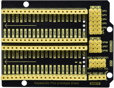
| Raspberry Pi Pico*1 | Raspberry Pi Pico Expansion Board*1 | USB Cable*1 |
 |
 |
|
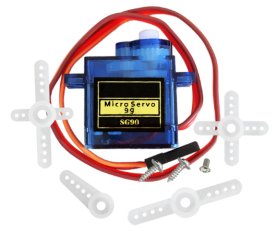
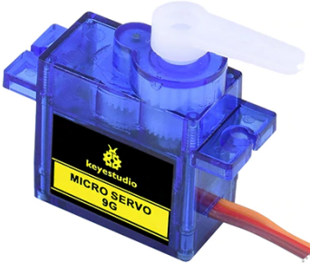
| Servo*1 | Jumper Wires |
Component Knowledge
Servo:
The servo is a kind of position servo driver, which is mainly composed of housing, circuit board, coreless motor, gear and position detector. The working principle is that the receiver or microcontroller sends a signal to the servo, which has an internal reference circuit that generates a reference signal with a period of 20ms and a width of 1.5ms, and compares the DC bias voltage with the voltage of the potentiometer to output voltage difference. The IC on the circuit board determines the direction of rotation, and then drives the coreless motor to start rotation and transmits the power to the swing arm through the reduction gear, while the position detector sends back a signal to determine whether it has reached the positioning. It is suitable for those control systems that require constant change of angle and can be maintained.
When the motor rotates at a certain speed, the potentiometer is driven by the cascade reduction gear to rotate so that the voltage difference is 0 and the motor stops rotating. The angle range of general servo rotation is 0 to 180 degrees.
The pulse period for controlling the servo is 20ms, the pulse width is 0.5ms to 2.5ms, and the corresponding position is -90° to +90°. The following is an example of a 180 degree servo.

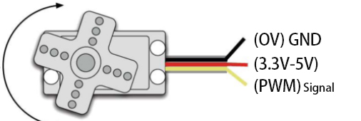
Servo motors have many specifications, but they all have three connecting wires, which are brown, red, and orange (different brands may have different colors). The brown is GND, the red is the positive power supply, and the orange is the signal line.
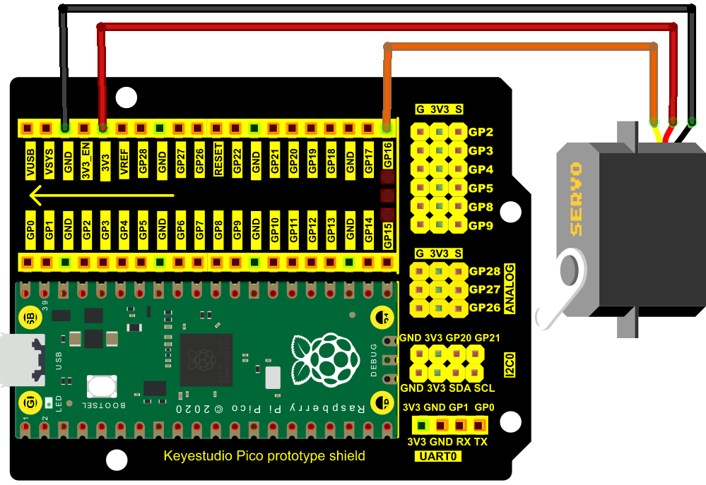
4. Wiring Diagram
When supplying the servo, please note that the power supply voltage should be 3.3V-5V. Make sure there are no errors when connecting the servo to the power supply.
5. Test Code
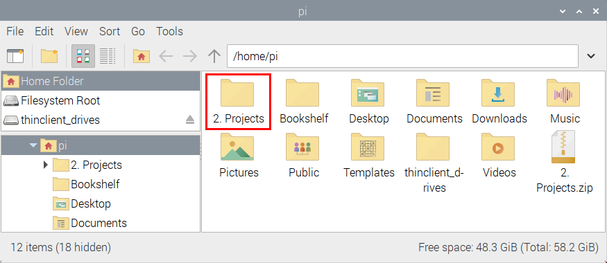
The code used in this project is saved in the file KS3025 Keyestudio Raspberry Pi Pico Learning Kit Complete Edition\3. Raspberry Pi System\Python_Tutorial\2. Projects\Project 19:Servo Sweep. You can move the code anywhere. We save the code to the pi folder of the Raspberry Pi system. The path: home/pi/2. Projects.
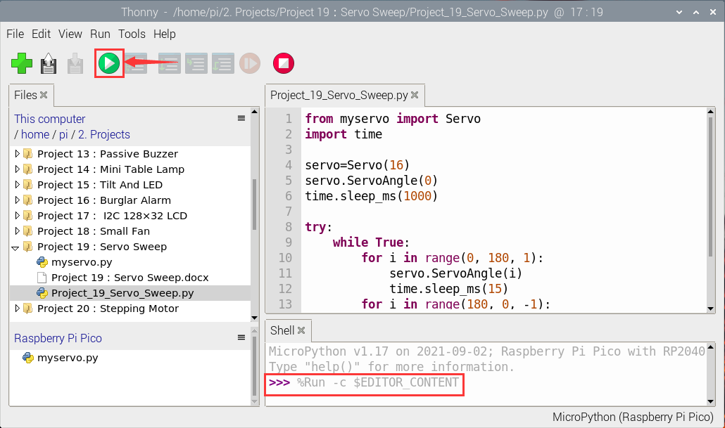
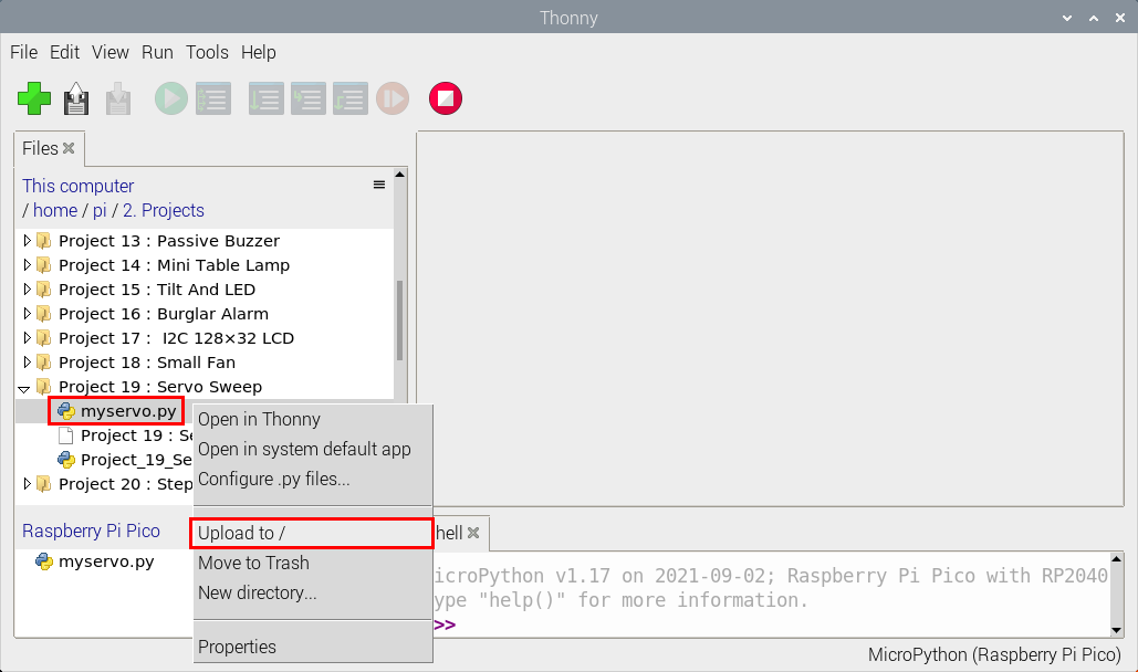
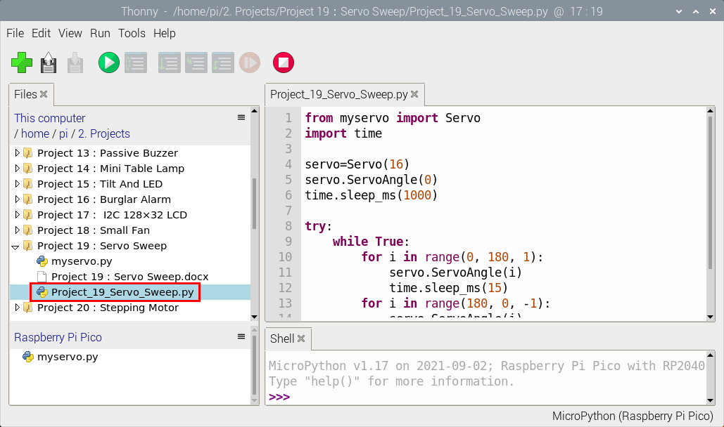
Open“Thonny”, click“This computer”→“home”→“pi”→“2. Projects”→“Project 19:Servo Sweep”. Select“myservo.py”,right-click and select“Upload to/”, waiting for the“myservo.py”to be uploaded to the Raspberry Pi Pico. And double-click the“Project_19_Servo_Sweep.py”.
from myservo import Servo
import time

servo=Servo(16)
servo.ServoAngle(0)
time.sleep_ms(1000)

try:
    while True:
        for i in range(0, 180, 1):
            servo.ServoAngle(i)
            time.sleep_ms(15)
        for i in range(180, 0, -1):
            servo.ServoAngle(i)
            time.sleep_ms(15)
except:
    servo.deinit()
6. Test Result
Ensure that the Raspberry Pi Pico is connected to the computer,click“ Stop/Restart backend”.
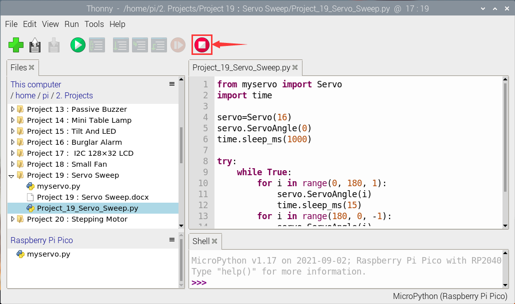
Click  “Run current script”, the code starts executing, we will see that the servo will rotate from 0° to 180°, then reverse direction to rotate from 180° to 0°in a loop.
Press“Ctrl+C”or click“ Stop/Restart backend”to exit the program.
“Run current script”, the code starts executing, we will see that the servo will rotate from 0° to 180°, then reverse direction to rotate from 180° to 0°in a loop.
Press“Ctrl+C”or click“ Stop/Restart backend”to exit the program.